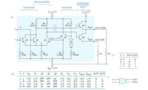
Ecl Nor Gate Circuit Diagram
Ecl gate nor transistor working explain describe turned obvious corresponding 8v input then any very if high diagram Study engineering: nor gate Conversion of nor gate to basic gates
How Logic Gates Work
Introduction to logic gates – projectiot123 esp32,raspberry pi,iot projects Or/nor gate of emitter coupled logic Emitter ecl logic coupled family circuit electronics
Emitter coupled logic (ecl)
5 km fm transmitter circuit diagramEmitter coupled logic gate nor Coupled emitter ecl transistor ttlEcl circuit basic logic presentation coupled emitter ppt powerpoint slideserve.
Emitter-coupled-logic (ecl): (3 marks) assume vbeCircuit diagram of the basic fan-out of one ecl or-nor gate. one input Nor gatesCircuit ecl logic coupled emitter simplified.

Logic ecl coupled emitter gate circuit nor vlsi table cml diagram 10k 10h families
The basics of emitter-coupled logicInverter emitter coupled ecl Describe a basic ecl nor gate and explain its working in short with theInside the am2901: amd's 1970s bit-slice processor.
Vlsi design: emitter coupled logicFunctional schematic of integrated circuits Emitter-coupled logicEmitter coupled logic family (ecl) ~ electronics and communication.

Conversion of nor gate to basic gates
Ecl gate nor logic emitter coupled dual fig learnabout electronics digitalVlsi design: emitter coupled logic Circuit nor transmitter circuitspedia logic gates electronicsLogic ecl nor gate table truth emitter coupled circuit diagram input 10k fig two.
Nor gate input eclHow logic gates work Ecl two input or/ nor gateDigital electronics.

Digital logic
Ecl implemented norNor gate logic gates truth table output introduction high technology its if Ecl nor/orCircuit ecl diagram gate input nor.
Nor gate circuit diagramNor schematic gate ic ecl integrated diagrams xor Nor input gate diagram convert multi logicNor circuit gates basic.

Ecl logic emitter coupled assume vbe solve
Logic coupled emitter ecl basics inverter articles buffer figureEcl circuit nor simulator .
.


PPT - Emitter-Coupled Logic PowerPoint Presentation, free download - ID

ECL NOR/OR - Online Circuit Simulator

PPT - Emitter-Coupled Logic PowerPoint Presentation - ID:61689

VLSI Design: Emitter Coupled Logic

digital logic - How can we convert multi-input NOR gate diagram to a 2

Conversion of NOR gate to Basic gates

Conversion of NOR gate to Basic gates